Download free music MP3s on genuine quality, the world’s largest online music catalogue, powered by your scrobbles. Free listening, videos, photos, The world’s largest online music catalogue, powered by your scrobbles. Free listening, videos, photos, stats, charts, biographies and concerts. stats, charts, biographies and concerts.
Sunday, January 12, 2025
Multi-Mode MIDI Step Sequencer – CDR Format – Part 3
This post revisits the "CDR format" (CD Rack Format) panel version of my Multi-Mode MIDI Step Sequencer. Part 1 detailed the build and testing of the panel. Part 2 updated and enhanced the Multi-Mode MIDI Step Sequencer code to run on the panel. …
A key issue was that I hadn't really documented the dimensions I'd used in the design of the original panel, but after finding the old cardboard cutout and comparing to my built panel I was able to reproduce the dimensions.
It also turns out that I haven't really listed the hole sizes I've been using for panels either, so that was part of the first task too.
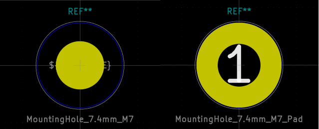
I had to create a custom KiCad part for an M7 hole. I based this on the existing M8 holes (one with a pad and one without).
The rest of the holes used, that match the connectors I'm using, are as follows:
Potentiometer
M7 (7.4mm) mounting hole
Audio Out
M8 (8.4mm) mounting hole
MIDI TRS
M6 (6.4mm) mounting hole
Toggle Switch
M7 (7.4mm) mounting hole
"Thonkiconn" Jack Socket
M6 (6.4mm) mounting hole
3mm LED
3mm mounting hole
5mm LED
5mm mounting hole
Power Switch
12.5mm diameter edge cut cutout
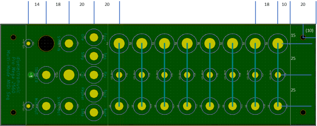
The key dimensions are indicated below. The whole panel is 250x80 mm with mounting holes 10x10mm from each corner and 20mm clearance top and bottom for mounting.
As I'm using a PCB design tool for the panel, I've included a rear GND zone, so left a small pad exposed near the bottom to solder to if required. I did think about using "pads" rather than plain holes to allow switches and potentiometers and so on to connect to the GND zone, but in the end opted for plain holes.
Note: there is one error on the final PCB - the toggle switch was designed with a M6 hole and actually I need an M7, so I had to widen it slightly.
There were a couple of complications with switching over, that I wouldn't have had with a new build:
The power switch needed desoldering and resoldering as the nut is on the inside. Unfortunately I managed to damage the click mechanism and on first try, it was quite unreliable latching in the on position. I had to replace it completely.
Two of the three-way switches had their nut/shaft fail on me - I managed to do up the nut most of the way, but not completely and then the threaded shaft started rotating meaning I could neither do it up or undo it. They work, they are fixed in, but they are a little wobbly which is really annoying! But I'd need to desolder a fair bit to replace them. They'll do for now. Sigh.
Some enhancements were possible too whilst updating the board:
I've added a 10nF capacitor across the terminals of the toggle switch to aid debouncing.
Other enhancements I'm considering that I might add at a later date:
Add capacitors across all pots for smoothing.
Add clamp Schottky diodes to the sync IN/OUT sockets, so they aren't just a direct connection to the microcontroller's GPIO ports. This was always something I meant to do anyway.
I thought this would be a straight swap and relatively straight forward to do. Unfortunately the use of cheap components caught up with me on this one.
Still, I think the result looks pretty good and it does all now work fine.


No comments:
Post a Comment